Here you’ll find answers to many of the common support requests we receive for the Atlas HD automated jacketed reactor product family. If you can’t find the answer you’re looking for, please contact the Support team.
Technical
-
What are the product dimensions and power requirements of Atlas HD?
Smallest vessel: 108cm H x 54cm W x 45cm D
Largest vessel: 115cm H x 58cm W x 45cm D
Power: 100-240 VAC, 50/60 Hz, 5A Fuse
-
What clamps are needed for each vessel size?
DN80: 50ml, 100ml, 250ml, 500ml, 1L, 2L, 3L
DN150: 1L, 2L, 3L, 5L
-
Is custom glassware available?
Yes, our expert glassblowers can design and manufacture custom glassware upon request
-
Are wetted parts chemically resistant?
All wetted parts are made from either glass, PTFE, FFKM or other similar fluoropolymers.
-
What circulators are Atlas HD compatible with?
Julabo Presto and Huber Pilot One circulators can be controlled directly from the Atlas HD base. For all other RS232 controlled circulators, PC/Atlas 1 software is required.
-
Circulator cooling water specification
Please find below the specification of the water used in water cooled circulator units.
Failure to ensure the water specification is met will result in poor performance from the circulator. In a worst case scenario, the circulator will simply show an error message and not work.
Huber Julabo Cooling Water Temperature 15DegC <20DegC Maximum Input Pressure 6 bar 6 bar Pressure Difference (In-Out) 3 bar + 3.5 to 6 bar pH at 25DegC 7 7 to 8.5 Suspended Matter – <30mg/Litre Size of suspended matter – <0.1 mm This information was collected from the Huber and Julabo service and support departments in Germany.
Please contact support if you require further information.
-
What is the pump valve syringe compatibility of the Atlas Syringe Pump XL?
The following Technical Note highlights the compatibility between syringes and valves for the Atlas XL pump.
-
What is the accuracy and resolution of the Atlas Pump?
This Technical Note provides detailed accuracy and resolution information
To be completely accurate, the following is the definition of how accurate the Atlas Syringe Pump system is:
Accuracy and Precision
Accuracy is described by two parameters: accuracy and precision. For both, the value given is expressed as a percentage of the full stroke of the syringe.
Accuracy measures how closely a dispensed amount of fluid corresponds to the ideal programmed value. Precision describes the ability of the drive to deliver the same quantity of fluid for the same size programmed dispenses.
By analogy, consider an archer shooting a group of arrows at a target. Precision is a measure of how closely the arrows are spaced on the target, called the size of the group.
Accuracy is a measure of how far the center of that group is from the center
of the target. The values for the Asia Syringe pumps are:- Accuracy 0.20% CV (typical, full-stroke), 0.4% max
- Precision 0.06% CV (typical, full-stroke), 0.12% max
Additional factors contributing to system accuracy are the total syringe size, any air bubbles or gaps, and any elasticity in the fluid path.
The syringe tolerance is a maximum ±1% of total volume.
This error contribution is proportional to the amount dispensed as a fraction of syringe volume. Air bubbles, gaps, and tubing elasticity can contribute errors due to compressibility or expansion of their volumes.
Such errors are proportional to the positive or negative fluid pressures in the fluid path.
Therefore, every stroke of the Atlas pump, we would expect 0.4% accuracy and 0.12% precision on each stroke. As mentioned above, external atmospheric events like bubbles, small temperature changes are what would cause the majority of errors.
Pump Stroke Resolution
The length of each stroke, irrespective of the syringe size, is 12000 steps. Therefore the set flow rate determines the steps per minute.
The data set by both the hardware and tweaked by the firmware gives a minimum smooth flow rate of 40 steps per second.
Similarly, the hardware and firmware give a less smooth flow rate of 1 step per second.
Example: A syringe is being used with a volume of 50 uL
Therefore:
Minimum smooth flow rate (uL/min) = 50 / 12000 x 40 x 60 = 10 uL/min
Min less smooth flow rate (uL/min) = 50 / 12000 x 1 x 60 = 0.25 uL/min
This calculation does not take into account any environmental factors (e.g. viscosity) which could affect the stability of the pump steps.
Therefore, we could not guarantee 100% accuracy in the less smooth flow rate area.
The flow rates we recommend are calculated as percentages of the syringe volume and are different for individual dosing modes.
In Continuous dosing mode we would recommend a minimum flow rate of 20% of the syringe volume per minute.
In Dual dosing mode, where the smoothness of the flow rate is less magnified is 1% of syringe volume.
-
How do I find out more about turbidity?
This Technical Note provides detailed turbidity information
-
What are the temperature specification of Syrris Glass Jacketed Vessels?
This Technical note provides detailed information about the temperature specification of Syrris Glass Jacketed Vessels
-
How do I change PIDs in the Atlas PC Software?
This Technical Note provides detailed information on changing the PIDs in the Atlas PC Software
-
How do I tweak a recipe?
This Technical Note provides detailed information on recipe tweaking
-
How do I collect useful support info from Atlas?
This Technical Note provides detailed information on collecting useful support info from Atlas
Summary
The information below will show you what data files are useful for support issues regarding the atlas and where they can be found.
Data Files
2.1 Obtaining Logs From The Atlas Base
1. Make sure the Atlas base is switched on and showing the idle screen

2. Insert the USB key into the Atlas base. The USB symbol will appear on the atlas display

3. Highlight the USB symbol and press the dial to enter the menu
 —->
—->
4. Rotate the dial and select the first item in the menu. Press the dial

5. Press the dial again to return to the USB menu. Next select item 3 ‘Copy Sys Logs
6. Select item two in the menu and press the dial to safely remove the USB key from the Atlas base

2.2 Viewing Logs From The Atlas Base
On the USB Key, there will now be a folder/directory called ‘Logs’. This folder is created by the atlas base when the above exercises is carried out. If there is already a folder called ‘Logs’, the Atlas base will put the put the logs into folders with time and date stamps as their names.
The date/time stamps are to be read from right to left. So in the example on the left, the highlighted folder is the most recent with a date/time stamp of 15:53 on the 17th of March 2008.
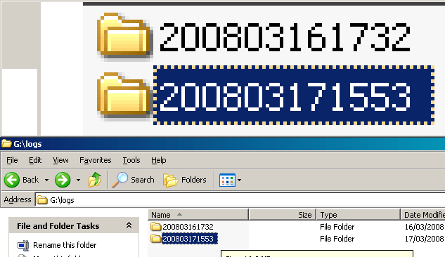
All log files copied over on to the USB key will have the extension *.log.
The extensions of the following files need to be renamed for you to be able to view them correctly. The *.log extensions for ATLAS_Data.log and ATLAS_System.log needs to be changed to *.csv. This will allow it to be opened in Microsoft Excel for viewing.
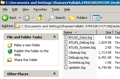
The remaining files can be viewed in Microsoft Word and contains detailed information about the Atlas base operating system and any connected hardware.
- For Syrris to form a detailed picture of an atlas base’s performance and functionality, all files need to be emailed to Syrris Support
- The combined file size of these files may be too big to attach to a single email
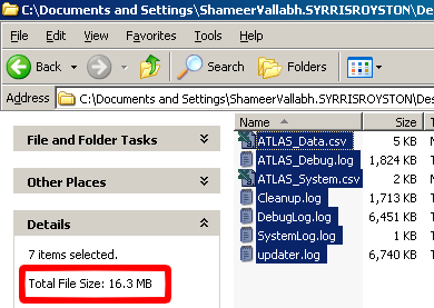
To send these files to Syrris Support, zip them up before emailing. If you are unsure about how to do this, contact contact support and further information will be provided.
2.3 Obtaining Logs from The Atlas Software
The experiment file and the data file from Atlas software can provide a wealth of information during a support issue. A lot of software support issues can usually be traced down to user error (Incorrect apparatus setup or incorrect recipe). But when the issue is more serious in nature, additional log files can help Syrris Support quickly diagnose and troubleshoot a problem.
Basic
In the Atlas software, simply opening the experiment file will not only load the apparatus setup but the recipe being used as well.
- Start the atlas software and open the experiment file in question
- Examine all connected hardware and port allocations (another common user error). Check for hardware that is present in the apparatus screen but not used in the recipe.
- Check for hardware that is present in the apparatus screen but not used in the recipe.Check the recipe. Make sure that there is nothing wrong with the recipe (set points, hardware being used, etc).Intermediate
- Check the recipe. Make sure that there is nothing wrong with the recipe (set points, hardware being used, etc).
Intermediate
The ‘Analysis’ section of the Atlas software can also be very useful in diagnosing an issue. It combines the information from and experiment file with a data file to show you clearly why something has gone wrong.
- Click on the ‘Analysis’ Tab in the atlas software and click the
 button located to the top right of the window
 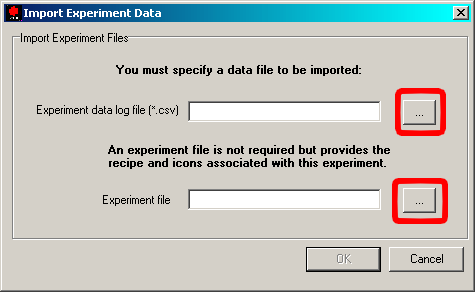 Click on the buttons with three dots (shown in the picture on the right) to select the data file and the experiment file to load. Note: In the open dialogue box, be mindful of the directory you are viewing. I.E. When you open the experiment file, the Atlas software may start by looking in the ‘Logs’ folder. You may need to navigate to the ‘Experiments’ folder
- Depending on how large the data files are, the atlas software will load the relevant data. Be patient and it will load.Once loaded, the Analysis window will behave much like the ‘Run’ window allowing you to drag and drop sensor data
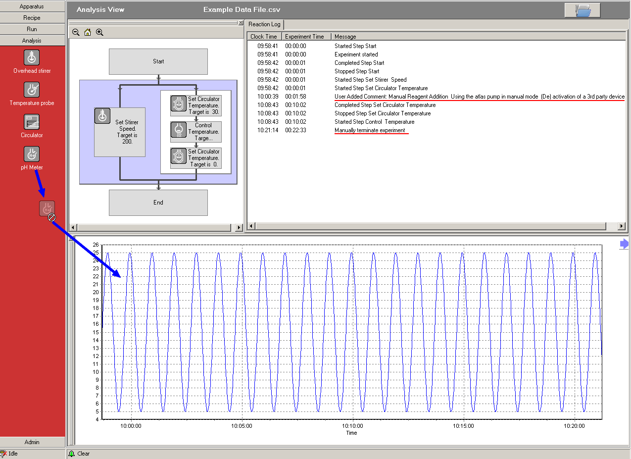 Once loaded, the Analysis window will behave much like the ‘Run’ window allowing you to drag and drop sensor data.The loaded data will also display the ‘Reaction Log’. Any error messages and reasons for recipe termination will be in here with a data/time stamp that can be correlated to specific steps in a recipe
The loaded data will also display the ‘Reaction Log’. Any error messages and reasons for recipe termination will be in here with a date/time stamp that can be correlated to specific steps in a recipe
Advanced
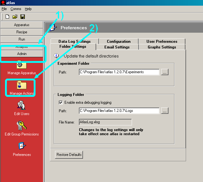
By switching on certain features in the Atlas software ‘Admin’ section, additional log files will be created during an experiment that provided a deeper level of information.
1. In the ‘Admin’ section of the Atlas software, select
 at the bottom of the list of the left
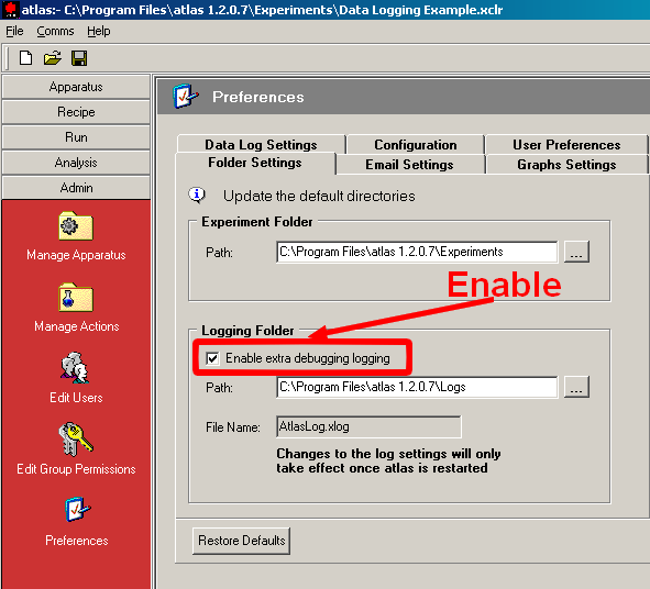 2. In the ‘Folder Settings’ tab, make sure the ‘Enable extra debugging logging’ box is ticked. Ideally, this box is ticked by the person carrying out the installation and the path is set to a separate folder that can be called ‘Debug Logs’. Enabling this function does not affect the visual and actual performance of the Atlas software
3. Enabling this feature will create a file called AtlasLog.xlog (default location is the ‘Logs’ folder). This file can provide the Syrris software team with information about the atlas software stability
4. In the ‘User Preferences’ tab, tick the box marked ‘Display low-level communications with devices’.
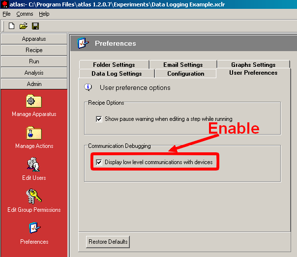
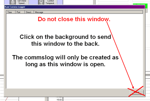
Activating this function will bring up a window automatically whenever a recipe is run. This window shows the low-level comms taking place between the atlas software and the hardware. Although it doesn’t affect any function of the atlas software, it must remain open. It can be minimized but please do NOT close this window. Again, ideally, this would be activated when the system is installed, but it depends on whether the customer minds the Comms logging window.
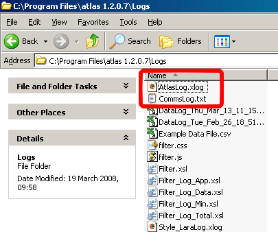
Once these features have been activated, two additional files will be generated whilst running a recipe. Email these files along with the experiment and data files to Syrris Support for further analysis.
Installation
-
How do I install Atlas PC Software?
This Document provides detailed information on the Atlas PC Software
-
How do I assemble filter vessels?
This Technical Note provides detailed information on the assembly of filter vessels
-
How do I use BOV correctly?
This Technical Note provides detailed information on the correct use of the BOV
-
How do I check the Atlas base version?
This Technical Note provides detailed information on checking the Atlas base version
-
How do I change syringes on the Atlas Syringe Pump?
This Technical Note provides detailed information on changing the Syringes on the Atlas Syringe Pump
Make sure the pump is in Dual Dosing mode.
1. Firstly, access the ‘OTHER COMMANDS’ in the pump menu

2. Select ‘EMPTY SYRINGE’ and empty the contents of the syringe safely

3. Now use the ‘FILL SYRINGE’ command and fill from a port that is not connected to any fluid

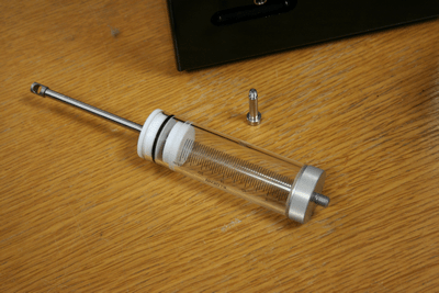
4. With the syringe plunger now at the bottom, unscrew the connecting screw and remove from the pump
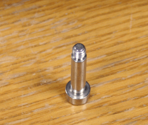
5. The Syringe can now be safely unscrewed and removed. Screw in the new syringe and fasten the screw through the plunger
6. Once the syringe is physically attached, go to the syringe pump menu and select ‘CONFIGURATION’
 —->
—->
7. In the configuration menu, change the syringe volume setting to your new syringe volume

8. Change the fill speed to approximately 4 times the working syringe volume. This will allow good performance across all the syringe types. You can change this value to better suit your needs
9. Finally, select ‘INITIALISE’ to store all the settings. The syringe pump is now ready for use.

-
Assembly instructions for the Atlas Filter Vessel
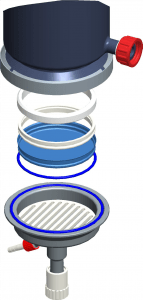
Figure 1: Exploded Diagram of Atlas Filter Vessel Assembly - The filter paper is shown in blue in Figure 1
- The filter paper should be 150 mm in diameter
- Fold the filter paper around the PTFE ring (C) and secure it in place using the O-ring (D)
- Place this assembly into the slotted support plate (E)
- Place the ring support (B) over this assembly to centralize the base section relative to the main vessel
- Offer up the fully assembled base section to the main vessel and secured in place with the clamp (A)
- The fully secured assembly is shown in cross section in Figure 2
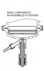
Figure 2 – Fully secured Atlas Filter Vessel assembly in cross-section Legend:
A: Quick-Release Clamp
B: PTFE Ring Support
C: PTFE Filter Paper Ring
D: Filter Paper O-Ring
E: Slotted Support Plate
-
Altering PID values in Atlas HD software
1. Changing the PID for Specific Steps
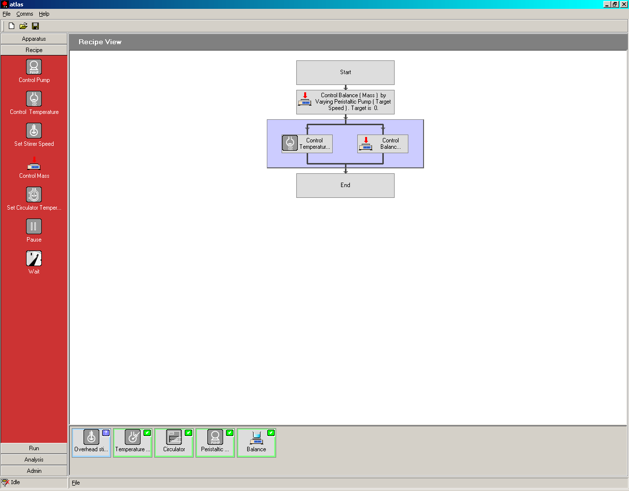
1.1. In the atlas software, go the recipe window.
Drag and drop an action onto the recipe to open up the step properties window.
If the step is already present, double click it to open the step properties window.
The step properties that use a PID control loop will have a PID user editable tab.
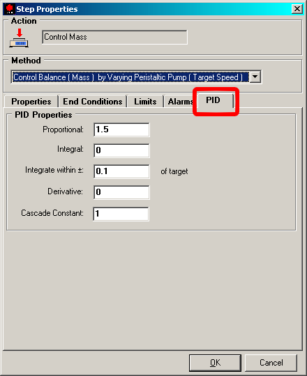
1.2. Click on the PID tab to access these values.The values contained in these boxes are the default PID values. If you change these values, you change the control properties FOR THAT STEP ONLY. Any other steps in the recipe will have their own default values and may need to be changed as well to suit the recipes needs.
2. Changing the default PID for an Action
Changing the default PID for an action will mean the chosen PIDs will be automatically selected when an action is used in a recipe file.
2.1. Firstly, click on the admin tab and then click on the manage actions to access all available actions.
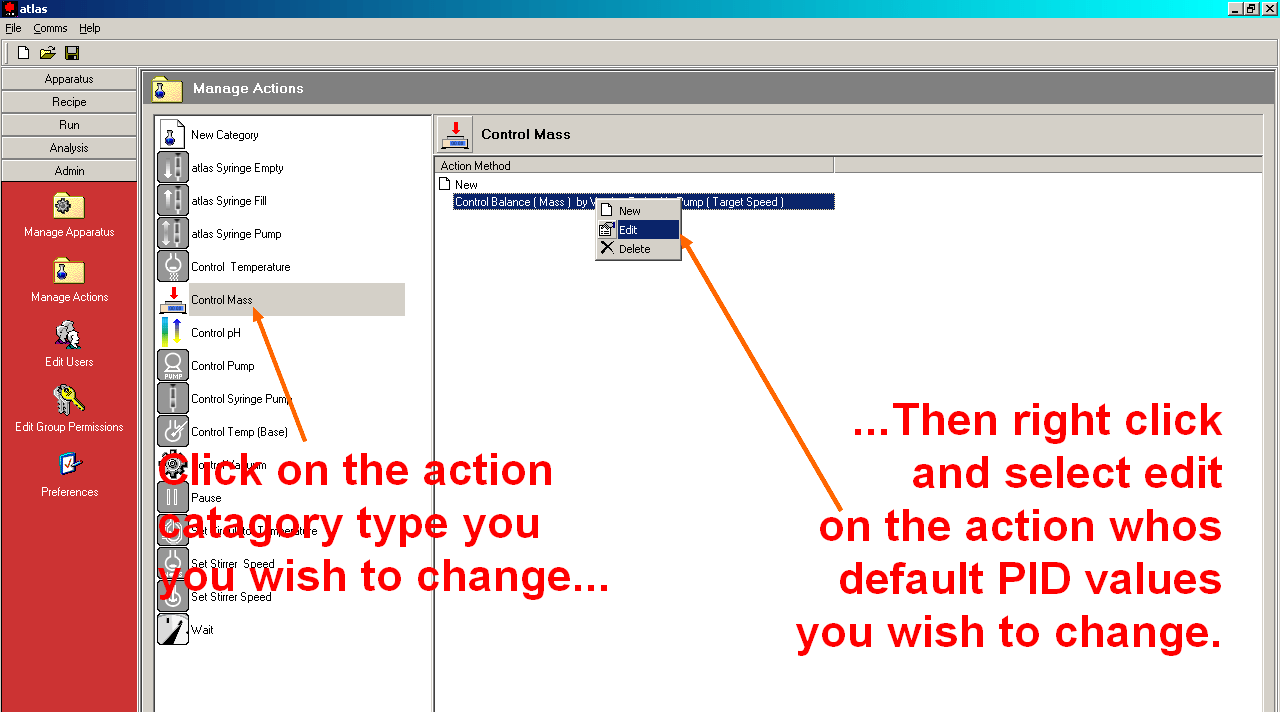
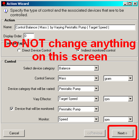
2.2. The action wizard should start up when you click the select the edit option. Do NOT change any of the values on the first window. Click next to move onto the next screen.
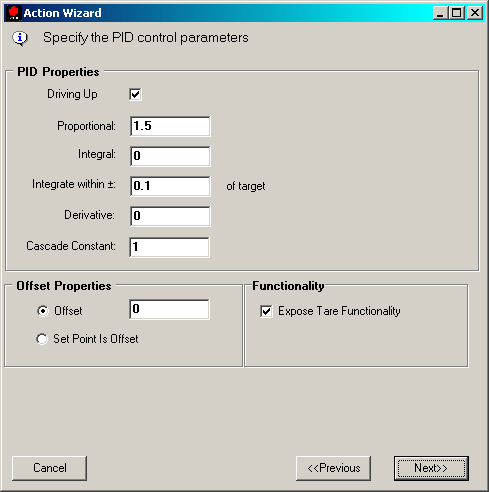
2.3. In this screen, you can enter proportional, integral and derivative values that will become the default every time an action is used in the recipe window.
Make note of the original values before you make any changes. The changes made here will have a direct influence in the way the hardware involved in this action will behave. Make note of any subsequent changes that are made. That way, should a set of parameters fail to deliver the correct behavior, the previous values can input carry on tuning.
Once finished, click next and next again to finish the wizard and save the values.
3. Basic Tuning Tips
If you type the words ‘PID tuning’ into an Internet search engine, you will find a plethora of websites with advice and software on how to obtain the perfect proportion, integral and derivative values for your given control loop. Here is a very basic method for tuning a system from first principals. In the example given below, temperature control is the loop.
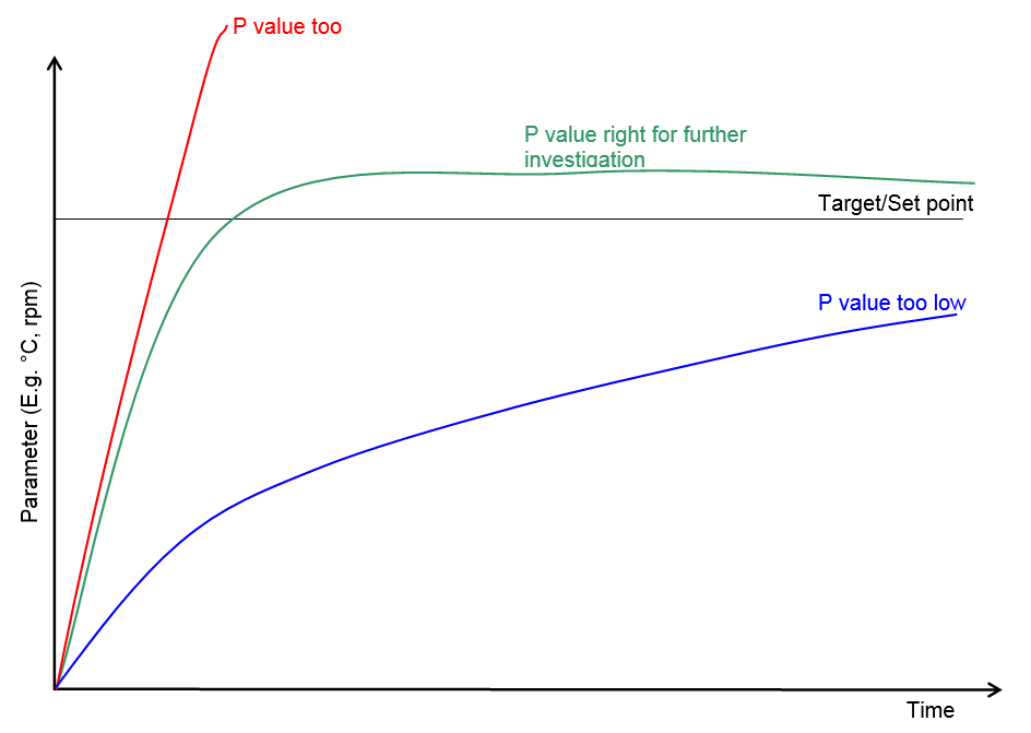
Proportional Value
Start with no proportional, integral or derivative values at all and enter a value for P. Write a very simple recipe which involves going to and maintaining a temperature e.g 10 – 20°C above room temperature.
Start by choosing a P value (e.g. 2) and see what effect that has on the profile. If P is too low, increase it and try the same step again. Do the reverse if the P value is too high and there is a massive overshoot.
Once you’ve got the correct level of overshoot, deduct 10% from you P value and move onto tuning the integral value.
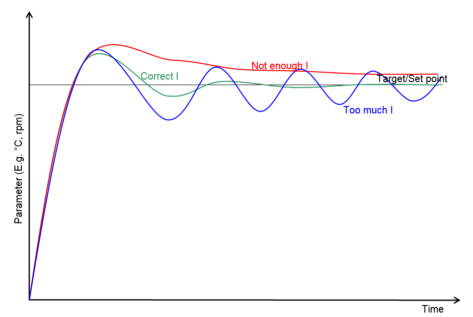
Integral Value
With your P value in place from the previous section, start increasing the I value to see what effect it has on the temperature profile. Increase or decrease the I value until the profile reaches the target /set point in the quickest time possible, with the minimum of overshoot and the minimum of oscillation. In most cases, oscillation will be negligible and no further tuning would be necessary.
Derivative
If the degree of oscillation is not suitable for your needs, start applying small quantities of D value. The D value should be used with caution as small changes can lead to very large effects to your control loop.
-
How to check the version of Atlas Base Software (Baseware)
a) To check the update has worked, select ‘M’ on the idle screen and press the Atlas dial

b) Select ‘Administration’

c) Select ‘Detected Hardware’

d) Select the ‘Atlas Base’

h) And finally, scroll down and check the atlas base version (Item 5 in the list)

Make a note of this version and let Syrris Support know when requested
Maintenance
-
How do I change Syringes on the Atlas Syringe Pump?
This Technical Note provides detailed information on changing the Syringes on the Atlas Syringe Pump
Make sure the pump is in Dual Dosing mode.
1. Firstly, access the ‘OTHER COMMANDS’ in the pump menu
2. Select ‘EMPTY SYRINGE’ and empty the contents of the syringe safely
3. Now use the ‘FILL SYRINGE’ command and fill from a port that is not connected to any fluid
4. With the syringe plunger now at the bottom, unscrew the connecting screw and remove from the pump
5. The Syringe can now be safely unscrewed and removed. Screw in the new syringe and fasten the screw through the plunger
6. Once the syringe is physically attached, go to the syringe pump menu and select ‘CONFIGURATION’
—->7. In the configuration menu, change the syringe volume setting to your new syringe volume
8. Change the fill speed to approximately 4 times the working syringe volume. This will allow good performance across all the syringe types. You can change this value to better suit your needs
9. Finally, select ‘INITIALISE’ to store all the settings. The syringe pump is now ready for use.
-
How do I replace a valve?
This Technical Note provides detailed information on replacing a valve
-
How do I take apart the Stirrer Seal?
This guide provides detailed information on taking apart the Stirrer Seal